Brushless motors and their drive systems share a deep connection, and numerous approaches have been developed to enhance the control and performance of these motors. In this article, we’ll explore two primary drive systems: square wave drive and sine wave drive.
| Motor Drive Systems |
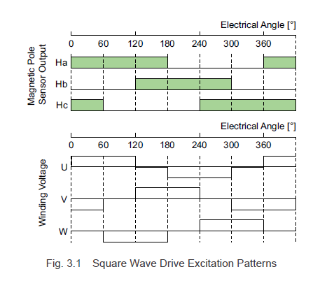
3.1.1 Square Wave Drive System (120° Conduction Mode)
Brushless motors come in a variety of drive configurations, and one commonly used method is the 120° conduction mode, which employs a square wave drive. As illustrated in Fig. 3.1, this technique switches the excitation states based on the combinations of hall effect IC outputs. While there may be speed fluctuations at lower speeds, the system offers high output power with a relatively simple circuit design. Consequently, it’s widely adopted for controlling brushless motors in office equipment and power devices.
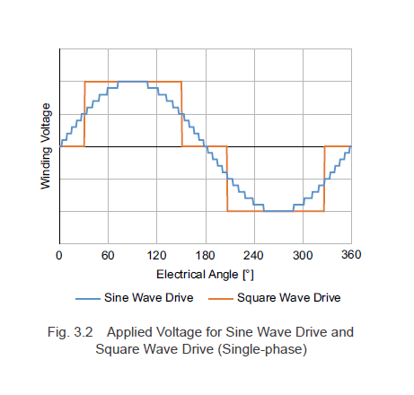
3.1.2 Sine Wave Drive System
The sine wave drive system precisely controls the applied voltage to create a sinusoidal motor current, as depicted in Fig. 3.2. This drive system minimizes torque ripple and ensures smooth rotation. Additionally, it reduces the noise produced by the motor.
However, performing sine wave driving requires accurate detection of the rotor magnetic pole positions. Historically, a high-resolution encoder was necessary for this task, but it increased both the overall motor length and its cost.
Today, instead of relying on encoders:
- Software processes the hall effect IC signals.
- Magnetic pole positions are detected using motor inductance and back EMF.
As a result, various methods can now be used to determine the magnetic pole positions and achieve sine wave driving.
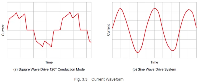
3.1.3 Current Waveforms for Each Type of Drive System
Figure 3.3 shows the actual current waveforms. The square wave drive exhibits some distortion compared to the applied voltage waveform, but its shape is closer to a sine wave than a true square wave. The sine wave drive, on the other hand, closely matches the applied voltage waveform.
Â
In upcoming posts, we’ll delve deeper into how different drive systems impact motor performance.
Â
|
Previous Post
|
Next Post
|


Â
Learn more about Oriental Motor's  hbspt.cta._relativeUrls=true;hbspt.cta.load(2284573, '0711e763-c067-4db9-8633-e45e46791b16', {"useNewLoader":"true","region":"na1"});
 hbspt.cta._relativeUrls=true;hbspt.cta.load(2284573, 'b434492d-37fd-4145-85d0-d88a2d703111', {"useNewLoader":"true","region":"na1"});
Â
Subscribe (top right corner) to receive monthly updates!
Â
A shell and tube heat exchanger is a type of heat exchanger that is commonly used for heating, cooling and condensing applications. lt consists of a shell with an internal bundle of tubes,which allows the hot and cold fluids to pass through the walls of the exchanger and exchange their energy. Shell and tube exchangers are classified in several ways, including design, operational construct, and construction materials. Mainly Fixed Tube Heat Exchanger, Floating Head Heat Exchanger, U-tube Heat Exchanger, and double tube heat exchanger.
The working principle of a shell and tube heat exchanger is relatively simple. The system is designed with two separate flows on either side of the heat exchanger. The primary flow of the hot fluid passes through the tubes, while the secondary flow of the cold fluid passes through the spaces between the tubes. Heat is then transferred from the hot side to the cold side via conduction, leading to an exchange of temperatures.
Shell and tube heat exchangers are normally used in process plants and used in a wide range of applications. A case in point is the cooling of condensates in refineries and nuclear power plants. In this application, condensate is heated using an external source and passed through the tube section of the heat exchanger. This condensate is then cooled and condensed as it passes through the shell side, where the heat is transferred to a cooling medium such as water, steam or oil.
Shell And Tube Heat Exchanger,Fixed Tube Sheet,Shell Tube Heat Exchanger,Split Ring Floating Head Heat Exchanger
Guangdong Jiema Energy Saving Technology Co.,Ltd , https://www.jmheatexchanger.com