There is a strong connection between the drive system and the characteristics of brushless motors. Over time, various methods have been developed to enhance the controllability and performance of these motors. In this post, we’ll explore two primary types of drive systems: square wave drive and sine wave drive.
| Motor Drive Systems |
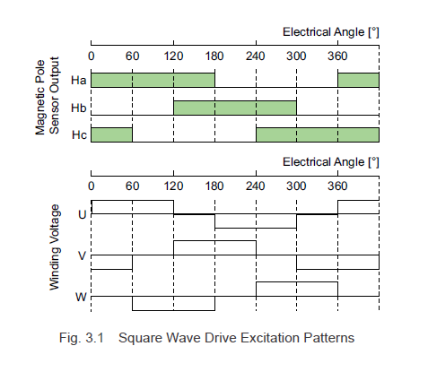
3.1.1 Square Wave Drive System (120° Conduction Mode)
Brushless motors come in many varieties, and one of the most common drive systems is the square wave drive, often referred to as the 120° conduction mode. As illustrated in Fig. 3.1, this method switches the excitation states based on the combinations of signals from Hall effect ICs. While there may be some speed fluctuations at lower speeds, it offers high output power with a relatively simple circuit design. For this reason, it’s widely used in controlling motors for office automation equipment and power tools.
3.1.2 Sine Wave Drive System
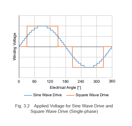
The sine wave drive system applies fine control over the voltage to ensure the motor current follows a sinusoidal pattern, as shown in Fig. 3.2. This drive system minimizes torque fluctuations and allows for smoother rotation. Additionally, it helps reduce noise during motor operation.
However, to implement sine wave driving, precise detection of the rotor’s magnetic pole positions is essential. Historically, this required high-resolution encoders, which increased both the length and cost of the motor.
Recently, instead of relying on encoders:
- Software has been developed to process signals from Hall effect ICs.
- Magnetic pole positions are detected using motor inductance and back EMF.
As a result, there are now multiple ways to detect magnetic pole positions and perform sine wave driving.
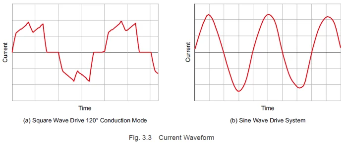
3.1.3 Current Waveforms for Each Type of Drive System
Fig. 3.3 shows the actual current waveforms. Although a square wave drive may appear distorted compared to the applied voltage waveform, it actually resembles sine waves more closely. On the other hand, a sine wave drive produces a waveform similar to the applied voltage.
Â
In the coming posts, we'll delve deeper into how the drive system influences motor performance.
Â
|
Previous Post
|
Next Post
|


Â
Learn more about Oriental Motor's  hbspt.cta._relativeUrls=true;hbspt.cta.load(2284573, '0711e763-c067-4db9-8633-e45e46791b16', {"useNewLoader":"true","region":"na1"});
 hbspt.cta._relativeUrls=true;hbspt.cta.load(2284573, 'b434492d-37fd-4145-85d0-d88a2d703111', {"useNewLoader":"true","region":"na1"});
Â
Subscribe (top right corner) to receive monthly updates!
Â
Brushless motors are widely used across various industries due to their efficiency and reliability. Their performance is significantly influenced by the type of drive system employed. The two most common drive systems—square wave and sine wave—are particularly noteworthy because they offer different advantages depending on the application requirements.
The square wave drive system, or 120° conduction mode, is favored for its simplicity and ability to produce high output power. However, it can experience speed fluctuations at lower speeds, making it less ideal for applications requiring precise control at all speeds. Despite this limitation, it remains popular in office automation equipment and power tools where high torque is needed.
On the other hand, the sine wave drive system provides a smoother and quieter operation. By ensuring the motor current follows a sinusoidal pattern, it reduces torque ripple and noise, leading to a more stable and efficient motor operation. This makes it suitable for applications where smooth motion is crucial, such as in robotics or precision machinery. However, implementing sine wave driving requires advanced techniques like software processing of Hall effect IC signals or using motor inductance and back EMF for position detection, which can add complexity and cost to the system.
Understanding the differences between these two drive systems allows engineers to choose the best solution for their specific needs. Whether it's prioritizing simplicity and cost-effectiveness or aiming for precision and quiet operation, the choice of drive system plays a critical role in optimizing the performance of brushless motors.
In future posts, we'll discuss additional aspects of brushless motor drive systems, including advanced control strategies and emerging technologies that continue to push the boundaries of what these motors can achieve. Stay tuned for more insights into the world of brushless motor technology!
Feel free to subscribe to our newsletter (located at the top right corner) to stay updated on the latest developments in brushless motor systems and related topics!
For further information on Oriental Motor's products, visit the links provided below:
hbspt.cta._relativeUrls=true;hbspt.cta.load(2284573, '0711e763-c067-4db9-8633-e45e46791b16', {"useNewLoader":"true","region":"na1"});
hbspt.cta._relativeUrls=true;hbspt.cta.load(2284573, 'b434492d-37fd-4145-85d0-d88a2d703111', {"useNewLoader":"true","region":"na1"});
A series of thin metal plates parallel to each other and pressed with a distance column are stacked to form a plate air-Air Heat Exchanger. The main components are heat transfer plates, outer frame sealing plates, compression device and so on.
The plate adopts full welding seal, flue gas and air cross flow between the plate for heat exchange. It`s suitable for air preheating and waste heat recovery in steel, chemical, electric power, battery and other industries, especially suitable for ultra-high temperature air to air heat exchange field.
Tranp`s Plate Air-Air Heat Exchanger is especially suitable for heat exchange between gas medium with high corrosion, high dust and high humidity.
The surface of the heat exchange plate is smooth with strong self-cleaning ability, so it is easy to clean. And multiple process is available, which is customized for different working conditions. Besides, the processing capacity can be as low as ten, but also as high as thousand CBM, therefore it`s widely used in waste heat recovery. What is more, the plate adopts advanced welding equipment and technology, combined use of resistance welding and manual welding between plates ensures that the weld joint is not easy to burst.
Air To Air Heat Exchanger,Air Preheater,Air Preheater In Boiler,Plate Type Air Heat Exchanger
Guangdong Jiema Energy Saving Technology Co.,Ltd , https://www.jmheatexchanger.com