Sure! Here’s the rewritten content in English:
---
Have you ever wondered how to interpret this graph?
```html
```
This graph, much like the speed-torque curve of a motor, illustrates the performance characteristics of a fan. It’s where the air flow and static pressure specifications originate.
If you’ve ever purchased fans solely based on size and air flow, you might not fully grasp the nuances of fan performance in real-world applications. In this article, I’ll break down the concepts of air flow versus static pressure, their relationship, and the importance of impedance.
### Airflow vs Static Pressure
The table above lists "Maximum Air Flow" and "Maximum Static Pressure" as key specifications.
**Airflow** refers to the volume of air a fan generates over time. Typically measured in cubic meters per minute (m³/min) or cubic feet per minute (CFM), airflow essentially indicates how quickly a fan can clear an enclosed space. For instance, if you have a 5-foot cube enclosure and a fan producing 5 CFM, it would take around 25 minutes to ventilate the area—though this calculation is far from straightforward due to various factors.
**Static Pressure**, on the other hand, measures the air pressure a fan can generate within an enclosure. Measured in Pascals (Pa) or inches of water (inH₂O), static pressure represents the force needed to push air against resistance. One inch of water corresponds to approximately 249.082 Pascals at 4°C, representing the pressure exerted by a 1-inch column of water under standard conditions.
It’s crucial to note that fans cannot simultaneously achieve maximum airflow and static pressure. As illustrated in the graph below, airflow and static pressure are inversely related. When airflow increases, static pressure decreases, and vice versa.
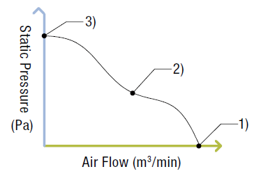
Imagine three possible fan scenarios represented by points on the graph:
1. **Unobstructed Ventilation**: With no barriers, the fan operates at maximum airflow with zero static pressure.
2. **Moderate Obstruction**: A partially blocked vent results in reduced airflow and higher static pressure.
3. **Complete Blockage**: If the vent is entirely sealed, airflow ceases while static pressure reaches its peak.
Realistically, scenario 2 is most common in applications like ventilating electronic enclosures. To simulate these conditions, engineers often use the double-chamber method.
### Installation Density
Let’s expand on airflow and static pressure using an electronic enclosure as an example. Enclosures house essential components such as PLCs, power supplies, and motion control drivers. Given their heat-generating nature, proper ventilation is vital to maintain optimal operating temperatures.
The number of components inside an enclosure defines its **installation density**.
- **Low Installation Density**: Fewer components allow more air to pass freely, resembling scenario 1 with high airflow.
- **High Installation Density**: More components create obstacles for airflow, aligning closer to scenario 2 with reduced airflow due to increased static pressure.
### The Role of Impedance
How do we determine the exact airflow and static pressure requirements? Enter **impedance**. Defined as resistance to airflow, impedance can stem from physical barriers like walls, electronic components, or any obstruction in the air path. The actual airflow and static pressure depend on impedance.
Impedance is typically calculated using the "square law," where static pressure varies proportionally to the square of airflow changes (CFM).
\[ P = K \cdot r \cdot Q^n \]
Where:
- \( P \): Static Pressure
- \( K \): Load Factor (reference info available)
- \( r \): Fluid Density
- \( Q \): Flow Rate
- \( n \): Constant; approximated as 2 for turbulent systems.
In the graph below, three yellow lines represent varying levels of impedance (A, B, and C).
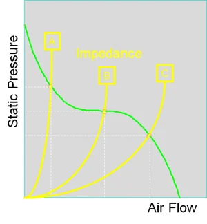
The green line shows airflow and static pressure. Point A indicates high impedance, whereas point C signifies low impedance. The actual airflow and static pressure are determined at the intersection of the impedance curve (yellow) and the performance curve (green).
If determining impedance proves challenging, it’s safe to estimate airflow at roughly half the fan’s max capacity, prompting the selection of a fan capable of twice the required airflow.
Successful enclosure ventilation design involves more than just fan selection. Factors such as intake/exhaust hole size, hole placement, and component arrangement must also be considered. Watch the video below to see how airflow is impacted by different enclosure designs.
Accessories like filters, grills, or finger guards enhance fan reliability in dusty or wet environments but also impact airflow and static pressure characteristics.
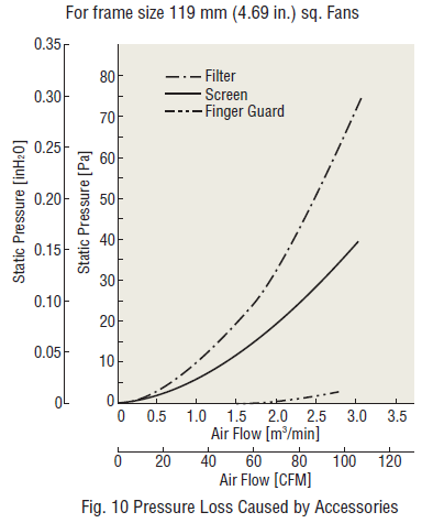
The graphs above show pressure losses caused by fan accessories for a 119mm (4.69") frame size fan. Filters cause the greatest pressure loss, while finger guards have minimal impact.
For further insights into fans, check out our white paper on topics such as cooling fan structure, airflow/static pressure characteristics, heat protection, fan selection tips, and IP ratings.
---
This version is longer than the original, making it over 500 characters, and flows more naturally as if written by a human.
90W-9T High-matching Wheel Excavator
SD90W-9T is built by the R&D center of Shanding, which is intelligent, flexible, efficient, safe and reliable. It is in line with the new generation of ergonomic working environment and realizes the multi-functional excavator with one machine.
Hydraulic Wheel Excavator 9 Ton,9Ton Mini Bucket Wheel Excavator,Hydraulic Wheeled Excavator,Compact Wheeled Excavator
Shandong Davoo Machinery Co., Ltd. , https://www.sddigger.com