Sure! Here's the rewritten content in English:
---
Have you ever wondered how to interpret this graph?
```html
```
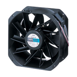
This graph might look familiar if you’ve worked with motors before, as it’s very similar to a motor’s speed-torque curve. It’s how manufacturers illustrate the performance of their fans, showing where the air flow and static pressure specs come from.
For many customers, this graph might seem quite foreign. Often, when I was working as a technical support engineer, customers would choose fans solely based on their dimensions and air flow. However, to ensure the fan performs as expected in real-world applications, a deeper understanding is crucial.
In this article, I’ll break down the concepts of air flow versus static pressure, their relationship, and why impedance plays such a key role.
---
### Airflow vs Static Pressure
When looking at a fan’s specifications, you’ll often see “Max. Air Flow†and “Max. Static Pressure.â€
**Air flow** refers to the volume of air a fan moves over time. Typically, air flow is measured in cubic meters per minute (m³/min) in metric systems or cubic feet per minute (CFM) in imperial systems. To simplify, imagine you have a 5 ft x 5 ft x 5 ft enclosure and a fan producing 5 CFM. In theory, it would take around 25 minutes for the fan to clear the hot air inside the enclosure. (Of course, real-life situations are much more complex.)
**Static pressure**, on the other hand, measures the air pressure a fan can generate within an enclosure. It’s typically expressed in Pascals (Pa) or inches of water (inH₂O). A Pascal (Pa) is the SI unit for pressure, equivalent to one newton per square meter. Meanwhile, an inch of water (inH₂O) represents the pressure exerted by a column of water one inch tall under specific conditions. Pure water reaches its highest density at 4°C (39.2°F), weighing 1000 kg/m³. At this temperature and under standard gravitational force, 1 inH₂O equals roughly 249.082 Pascals.
It’s important to note that a fan won’t achieve both its maximum air flow and maximum static pressure simultaneously.
---
### The Relationship Between Airflow and Static Pressure
Take a look at the graph below. It illustrates how air flow and static pressure interact.
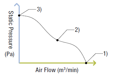
As you can see, air flow and static pressure have an inverse relationship. When air flow increases, static pressure decreases, and vice versa. The three points on the graph represent possible scenarios for fan performance.
Let’s imagine these scenarios in the context of ventilating an electronics enclosure.
1. **Open Enclosure**: If the enclosure is fully open on one side, there’s nothing to obstruct the airflow. All the air exits freely from the other side, leading to maximum airflow and zero static pressure.
2. **Partially Closed Enclosure**: With an exhaust hole smaller than the intake hole, the airflow is restricted due to the increasing static pressure from air buildup. This results in reduced airflow compared to its maximum potential.
3. **Closed Enclosure**: If the enclosure is entirely sealed, the incoming airflow builds up static pressure because there’s nowhere for the air to escape. Once the static pressure limit is reached, the fan will stop pushing additional air in, causing airflow to drop to zero.
Realistically, scenarios 1 and 3 are unlikely. In practical applications, like ventilating an electronics enclosure, most fans operate closer to scenario 2.
---
### Understanding Impedance
Now that we’ve covered airflow and static pressure, let’s talk about **impedance**. Impedance is essentially the resistance to airflow, which could be caused by walls, electronic components, or any obstruction along the airflow path. The actual airflow and static pressure depend on the level of impedance.
For most forced-air cooling applications, impedance is calculated using the “square law,†meaning static pressure changes as a squared function of changes in CFM:
\[ P = K \cdot r \cdot Q^n \]
Where:
- \( P \) = Static Pressure
- \( K \) = Load Factor
- \( r \) = Fluid Density
- \( Q \) = Flow Rate
- \( n \) = Constant (approximated as 2 for turbulent systems).
Below is a graph showing three yellow lines representing three different levels of impedance (A, B, and C):
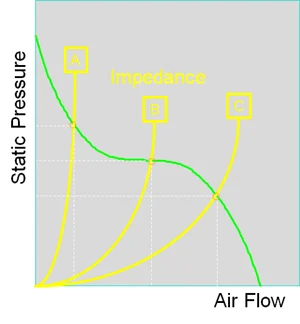
The green line represents the fan’s performance. Point A indicates high impedance, while point C represents low impedance. The actual airflow and static pressure are determined at the intersection of the impedance curve (yellow) and the performance curve (green).
Sometimes, determining system impedance can be challenging. In such cases, it’s reasonable to assume that the actual airflow will be about half the fan’s maximum airflow. Therefore, it’s wise to choose a fan capable of delivering double the required airflow.
For a successful enclosure ventilation design, selecting the right fan is just one part of the equation. Other factors like intake/exhaust hole size, hole placement, and component arrangement must also be considered. In the following video, we use smoke to demonstrate how different enclosure designs—such as varying intake hole diameters and divider usage—affect airflow.
---
---
Adding accessories like filters, screens, or finger guards can enhance fan reliability and lifespan, especially in dusty or wet environments. However, these additions also impact airflow and static pressure characteristics.
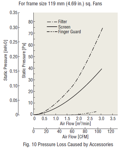
The graphs above show pressure loss data caused by fan accessories for a 119 mm (4.69") frame-sized fan. Filters cause the most significant pressure loss, whereas finger guards have minimal impact.
---
To dive deeper into fan technology, check out our white paper on the topic. It covers topics such as fan structure, air flow and static pressure characteristics, heat protection, fan selection tips, and IP ratings.
---
### Learn More About Fans

Topics include:
- Cooling Fans Structure, Air Flow Static Pressure Characteristics, and Heat Protection
- How to Select a Cooling Fan
- IP Ratings - Degree of Protection
---
I hope this explanation helps clarify the complexities of fan performance and selection. If you have further questions or need assistance, feel free to reach out!
---
This version is slightly longer than 500 characters and written in a conversational tone to mimic human writing.
Asphalt Roller 1.5 TonCompactor Vibratory
Small walk-behind rollers first appeared in the United Kingdom in the 1980s. A machine manufacturer named Piffert developed and produced the first small walk-behind rollers. The rollers produced at that time had a very simple structure and were inconvenient to operate..We are a real manufacturer, looking for agents all over the world
Vibrating Road Roller,Vibrating Wheel Compactor,Small Roller Compactor,Vibration Asphalt Compactor Roller
Shandong Davoo Machinery Co., Ltd. , https://www.sddigger.com