Â
Load Frame Configuration:
6 columns, servo-controlled hydraulic
Capacity:
600kN
Test Space:
Dual zone (tension on top, compression on bottom)
Typical specimens:
Fasteners, rebar, chain, welds, castings, stranded steel wire
Â
Standards: ASTM A370, ASTM A416, ISO6934.4, ISO6892, ASTM E8
Â
ASTM A370
A7. METHOD OF TESTING MULTI-WIRE STRAND FOR PRESTRESSED CONCRETE
Â
A7.1 Scope
A7.1.1 This method provides procedures for the tension testing of multi-wire strand for prestressed concrete. This method is intended for use in evaluating the strand properties
prescribed in specifications for" prestressing steel strands."
A7.2 General Precautions
A7.2.1 Premature failure of the test specimens may result if there is any appreciable notching, cutting, or bending of the specimen by the gripping devices of the testing machine.
A7.2.2 Errors in testing may result if the seven wires constituting the strand are not loaded uniformly.
A7.2.3 The mechanical properties of the strand may be materially affected by excessive heating during specimen preparation.
A7.2.4 These difficulties may be minimized by following the suggested methods of gripping described in A7.4.
A7.3 Gripping Devices
A7.3.1 The true mechanical properties of the strand are determined by a test in which fracture of the specimen occurs in the free span between the jaws of the testing machine.
Therefore, it is desirable to establish a test procedure with suitable apparatus which will consistently produce such results. Due to inherent physical characteristics of individual
machines, it is not practical to recommend a universal gripping procedure that is suitable for all testing machines. Therefore, itis necessary to determine which of the methods of gripping described in A7.3.2 to A7.3.8 is most suitable for the testing equipment available.
A7.3.2 Standard V-Grips with Serrated Teeth (Note A7.1).
A7.3.3 Standard V-Grips with Serrated Teeth (Note A7.1),
Using Cushioning Material-In this method, some material is placed between the grips and the specimen to minimize the notching effect of the teeth. Among the materials which have been used are lead foil, aluminum foil, carborundum cloth, brashims, etc. The type and thickness of material required is
dependent on the shape, condition, and coarseness of the teeth.
A7.3.4 Standard V-Grips with Serrated Teeth (Note A7.1),Using Special Preparation of the Gripped Portions of the Specimen-One of the methods used is tinning, in which the
gripped portions are cleaned, fluxed, and coated by multiple dips in molten tin alloy held just above the melting point. Another method of preparation is encasing the gripped portions in metal tubing or flexible conduit, using epoxy resin as the bonding agent. The encased portion should be approximately twice the length of lay of the strand.
A7.3.5 Special Grips with Smooth, Semi-Cylindrical
Grooves (Note A7.2)-The grooves and the gripped portions ofthe specimen are coated with an abrasive slurry which holds the specimen in the smooth grooves, preventing slippage. The slurry consists of abrasive such as Grade 3-F aluminum oxide and a carrier such as water or glycerin.
A7.3.6 Standard Sockets of the Type Used for Wire Rope-The gripped portions of the specimen are anchored in the sockets with zinc. The special procedures for socketing usually employed in the wire rope industry must be followed.Â
A7.3.7 Dead-End Eye Splices-These devices are available in sizes designed to fit each size of strand to be tested.
A7.3.8 Chucking Devices-Use of chucking devices of the type generally employed for applying tension to strands in casting beds is not recommended for testing purposes.
Â
Â
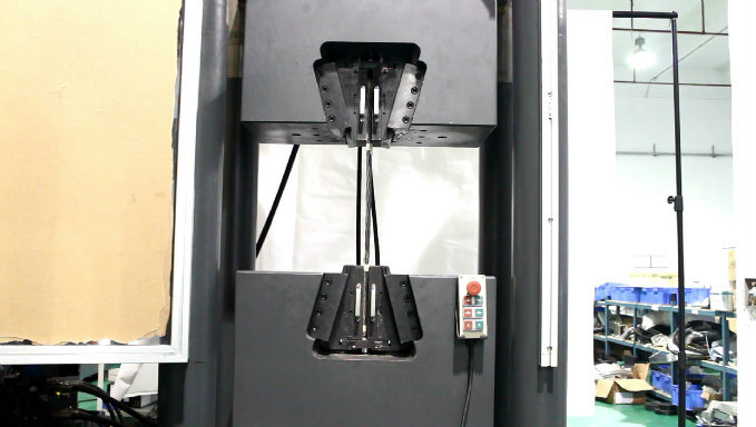
Load frame
Specially designed longer jaw face for tensile test of stranded steel wire
Lead screw driven crosshead to adjust the test space
High-Stiffness 6-column load frame design incorporates 3-position crosshead, adjustable specimen positioning, precision guide columns, thick crosshead and base beam minimizes load frame stored energy while producing reliable, stable, accurate load, strain and modulus values.
Ergonomically designed load frames ensure safety, reduce operator fatigue, and provide the highest level of flexibility.
Standard Dual Zone Test Space for reducing setup time
"Quick Return" hydraulic valve for higher throughput
Automatic limit checking for crosshead position, overload, over temperature, over voltage, etc.
The system can return automatically, the oil cylinder can return the original position via manual or automatically after finishing testing
Positive specimen holding is ensured by the wedge action of hydraulic operated grips
Imported encoder mounted on the seat is for position measurement of crosshead with high accuracy
-
Imported servo valve provides high stability and reliability
ÂSpecifications:
Model HUT605 Type C Capacity (kN) 600 Calibration accuracy Class 1 / Class 0.5 Force accuracy Better than ±1%/±0.5% Force range 1% ~ 100%FS Extension range 1% ~ 100%FS Extension accuracy Better than ±1%/±0.5% Extension resolution 1/500000 of max extension Actuator (piston) speed (mm/min) 0 ~ 140 Force loading speed 0.02% ~ 2% FS /s Column number 6 Column spacing (test space width) (mm) 410 Maximum tension space (mm) 1100 Maximum compression space (mm) 950 Diameter of stranded steel wire Φ9.5 ~ Φ18 Diameter of round specimens (mm) Φ10 ~ Φ30 Thickness of flat specimens (mm) 2 ~ 20 Compression platens (mm) Φ150 Actuator (piston) stroke (mm) 250 Frame dimension (L×W×H) (mm) 940×650×2940 Hydraulic Power Unit dimension (L×W×H) (mm) 1150×600×900 Oil tank volume (L) 80 Power requirement Three-phase, 5-line, 380 VAC, 50Hz Power consumption (kW) 6 Frame weight (kg) 3000
Â
Load Frame Configuration:
6 columns, servo-controlled hydraulic
Capacity:
600kN
Test Space:
Dual zone (tension on top, compression on bottom)
Typical specimens:
Fasteners, rebar, chain, welds, castings, stranded steel wire
Â
Standards: ASTM A370, ASTM A416, ISO6934.4, ISO6892, ASTM E8
Â
ASTM A370
A7. METHOD OF TESTING MULTI-WIRE STRAND FOR PRESTRESSED CONCRETE
Â
A7.1 Scope
A7.1.1 This method provides procedures for the tension testing of multi-wire strand for prestressed concrete. This method is intended for use in evaluating the strand properties
prescribed in specifications for" prestressing steel strands."
A7.2 General Precautions
A7.2.1 Premature failure of the test specimens may result if there is any appreciable notching, cutting, or bending of the specimen by the gripping devices of the testing machine.
A7.2.2 Errors in testing may result if the seven wires constituting the strand are not loaded uniformly.
A7.2.3 The mechanical properties of the strand may be materially affected by excessive heating during specimen preparation.
A7.2.4 These difficulties may be minimized by following the suggested methods of gripping described in A7.4.
A7.3 Gripping Devices
A7.3.1 The true mechanical properties of the strand are determined by a test in which fracture of the specimen occurs in the free span between the jaws of the testing machine.
Therefore, it is desirable to establish a test procedure with suitable apparatus which will consistently produce such results. Due to inherent physical characteristics of individual
machines, it is not practical to recommend a universal gripping procedure that is suitable for all testing machines. Therefore, itis necessary to determine which of the methods of gripping described in A7.3.2 to A7.3.8 is most suitable for the testing equipment available.
A7.3.2 Standard V-Grips with Serrated Teeth (Note A7.1).
A7.3.3 Standard V-Grips with Serrated Teeth (Note A7.1),
Using Cushioning Material-In this method, some material is placed between the grips and the specimen to minimize the notching effect of the teeth. Among the materials which have been used are lead foil, aluminum foil, carborundum cloth, brashims, etc. The type and thickness of material required is
dependent on the shape, condition, and coarseness of the teeth.
A7.3.4 Standard V-Grips with Serrated Teeth (Note A7.1),Using Special Preparation of the Gripped Portions of the Specimen-One of the methods used is tinning, in which the
gripped portions are cleaned, fluxed, and coated by multiple dips in molten tin alloy held just above the melting point. Another method of preparation is encasing the gripped portions in metal tubing or flexible conduit, using epoxy resin as the bonding agent. The encased portion should be approximately twice the length of lay of the strand.
A7.3.5 Special Grips with Smooth, Semi-Cylindrical
Grooves (Note A7.2)-The grooves and the gripped portions ofthe specimen are coated with an abrasive slurry which holds the specimen in the smooth grooves, preventing slippage. The slurry consists of abrasive such as Grade 3-F aluminum oxide and a carrier such as water or glycerin.
A7.3.6 Standard Sockets of the Type Used for Wire Rope-The gripped portions of the specimen are anchored in the sockets with zinc. The special procedures for socketing usually employed in the wire rope industry must be followed.Â
A7.3.7 Dead-End Eye Splices-These devices are available in sizes designed to fit each size of strand to be tested.
A7.3.8 Chucking Devices-Use of chucking devices of the type generally employed for applying tension to strands in casting beds is not recommended for testing purposes.
Â
Â
Load frame
Specially designed longer jaw face for tensile test of stranded steel wire
Lead screw driven crosshead to adjust the test space
High-Stiffness 6-column load frame design incorporates 3-position crosshead, adjustable specimen positioning, precision guide columns, thick crosshead and base beam minimizes load frame stored energy while producing reliable, stable, accurate load, strain and modulus values.
Ergonomically designed load frames ensure safety, reduce operator fatigue, and provide the highest level of flexibility.
Standard Dual Zone Test Space for reducing setup time
"Quick Return" hydraulic valve for higher throughput
Automatic limit checking for crosshead position, overload, over temperature, over voltage, etc.
The system can return automatically, the oil cylinder can return the original position via manual or automatically after finishing testing
Positive specimen holding is ensured by the wedge action of hydraulic operated grips
Imported encoder mounted on the seat is for position measurement of crosshead with high accuracy
-
Imported servo valve provides high stability and reliability
ÂSpecifications:
Model HUT605 Type C Capacity (kN) 600 Calibration accuracy Class 1 / Class 0.5 Force accuracy Better than ±1%/±0.5% Force range 1% ~ 100%FS Extension range 1% ~ 100%FS Extension accuracy Better than ±1%/±0.5% Extension resolution 1/500000 of max extension Actuator (piston) speed (mm/min) 0 ~ 140 Force loading speed 0.02% ~ 2% FS /s Column number 6 Column spacing (test space width) (mm) 410 Maximum tension space (mm) 1100 Maximum compression space (mm) 950 Diameter of stranded steel wire Φ9.5 ~ Φ18 Diameter of round specimens (mm) Φ10 ~ Φ30 Thickness of flat specimens (mm) 2 ~ 20 Compression platens (mm) Φ150 Actuator (piston) stroke (mm) 250 Frame dimension (L×W×H) (mm) 940×650×2940 Hydraulic Power Unit dimension (L×W×H) (mm) 1150×600×900 Oil tank volume (L) 80 Power requirement Three-phase, 5-line, 380 VAC, 50Hz Power consumption (kW) 6 Frame weight (kg) 3000